FRANC Hardware
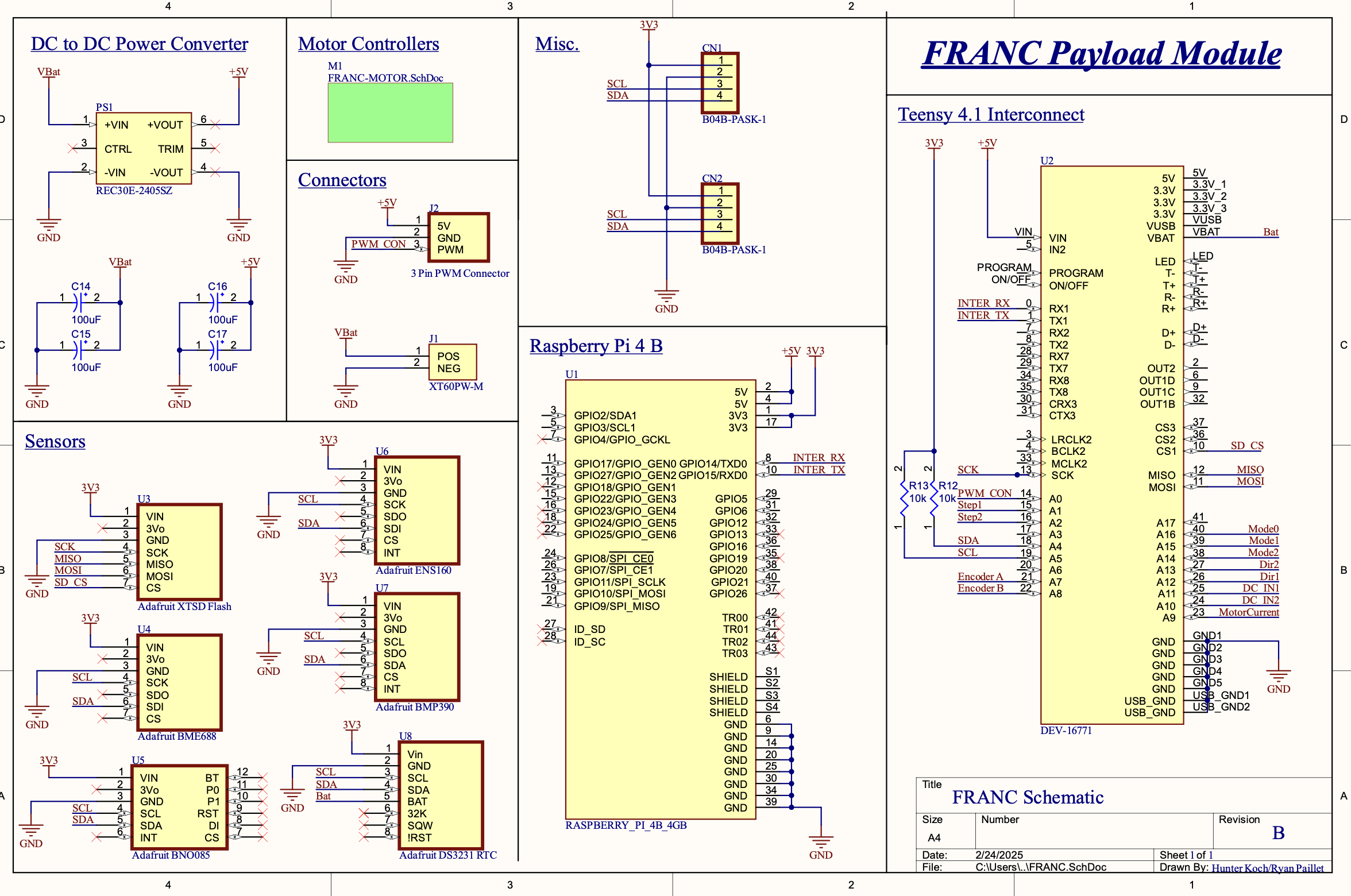
The FRANC system implements a high-speed, embedded-to-SBC data transfer architecture based on a serial interconnect between a periphery microcontroller (Teensy 4.1) and a single-board computer (Raspberry Pi).
The Teensy 4.1 communicates with the Raspberry Pi via its hardware UART pins at a nominal rate of 2 Mbaud. The UART is configured for USB–TTL conversion at the Teensy side, presenting as a TTY device to the Raspberry Pi. This data channel transmits structured telemetry in JSON-encoded form. The choice of 2 Mbaud was determined through throughput modeling to provide sufficient margin for high-rate sensor updates without incurring unacceptable serialization latency or excessive packet buffering. At this rate, JSON serialization overhead (~30–50% depending on field names and numeric resolution) still permits a full suite of environmental parameters to be transmitted in near-real time.
FRANC System
Data acquisition and polling methodology
The Teensy microcontroller interfaces with a heterogeneous set of environmental and inertial sensors, sampled at 100 Hz. This update rate was selected as a compromise between the Nyquist criteria for the fastest-varying quantities (e.g., acceleration and pressure derivatives) and the computational/communication bandwidth constraints of the system.
Sensor polling is implemented via timeout-based acquisition scheduling, whereby the firmware maintains an internal timing model of each sensor’s register-update interval. Rather than blindly reading on a fixed clock, the system queries a given device only after the predicted register update event, reducing unnecessary bus transactions and minimizing I²C/SPI bus contention. This approach is particularly beneficial for high-rate, multi-sensor fusion systems where synchronous polling would otherwise saturate shared buses.
SBC-side processing and modulation chain
Upon receipt of the JSON telemetry stream, the Raspberry Pi performs:
- Deserialization – Parsing incoming JSON strings into native data structures.
- Field extraction and APRS packet assembly – Mapping decoded sensor values into an AX.25 UI frame payload conforming to the APRS specification.
- Software modulation – Encoding the AX.25 packet into an AFSK-1200 baseband waveform in software.
- Sample transfer to RF hardware – Streaming the baseband samples over a USB 2.0 bulk interface to a HackRF SDR.
Root cause of in-flight transmission failure
At competition, the APRS transmission path failed primarily due to mechanical disconnect of the HackRF from the Raspberry Pi’s USB-A port. The Raspberry Pi and its associated cabling were mounted on one of the payload’s structural supports rather than centrally on the main PCB, a design concession driven by the circular PCB layout and the mechanical footprint of the centrally-mounted dipole antenna.
During high-G acceleration events in flight, the lack of strain relief and the inherent mechanical weakness of USB-A friction-fit connectors allowed the cable to unseat, interrupting the RF link. This mechanical failure cascaded into total loss of APRS telemetry, despite continued operation of the sensor acquisition subsystem.
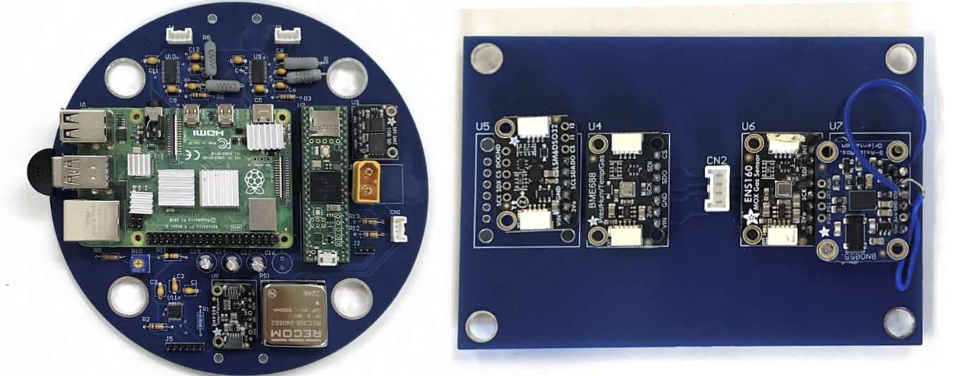
FRANC – Main Sensor System
Motor control subsystem
A dedicated motor control PCB, designed to actuate a secondary mechanical subsystem, was integrated but never activated in flight. The actuation mechanism it was intended to drive failed preemptively, rendering the control electronics unused. This subsystem consisted of a dedicated microcontroller, MOSFET H-bridge drivers, and interface logic, but it was electrically isolated from the telemetry path.
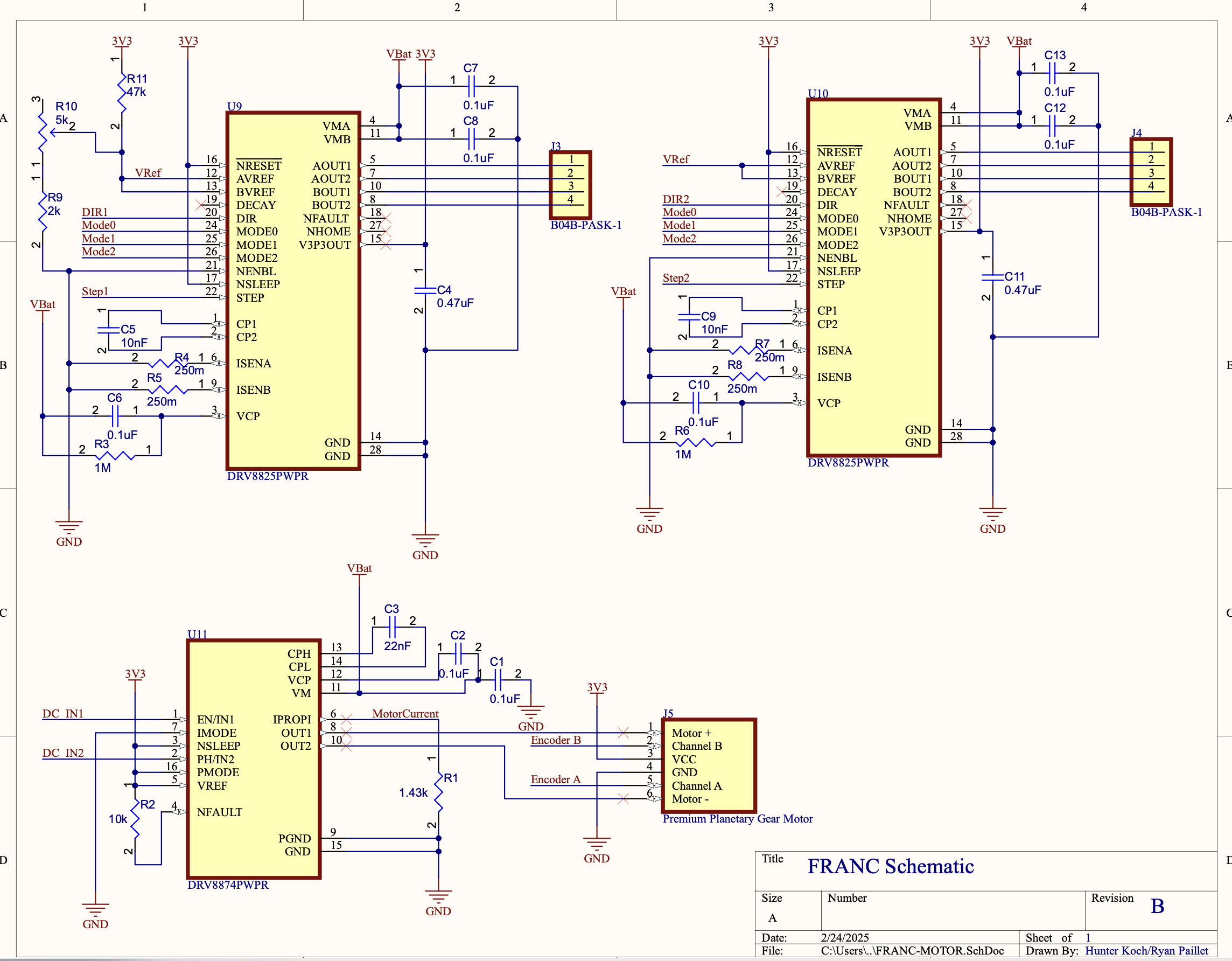
FRANC – Motor Control (Unused in Flight)
Main PCB configuration
The main PCB was produced in a circular form factor to fit within the payload tube’s available volume. Due to the presence of the dipole antenna running axially through the center, the Raspberry Pi had to be relocated to a structural support pole along the payload’s periphery. This relocation inadvertently placed the USB-A connection to the HackRF in a mechanically vulnerable position during high-G flight conditions.
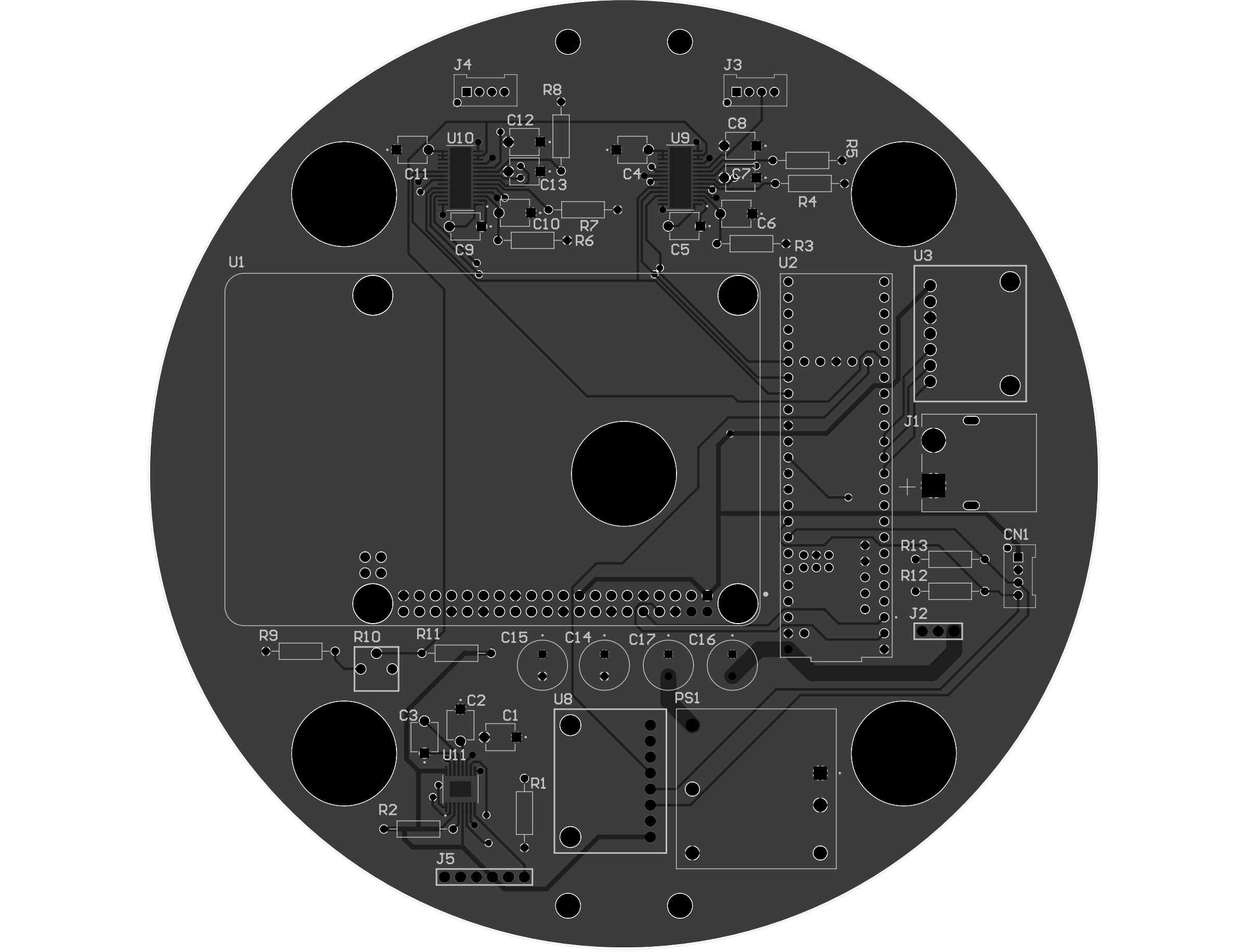
FRANC – Main PCB (Circular Layout)
External peripheral board
An auxiliary external board was included in the payload stack but has historically exhibited low first-pass bring-up reliability. In both lab and field tests, achieving stable operation required multiple firmware and hardware interventions, resulting in uncertainty regarding its operational readiness.
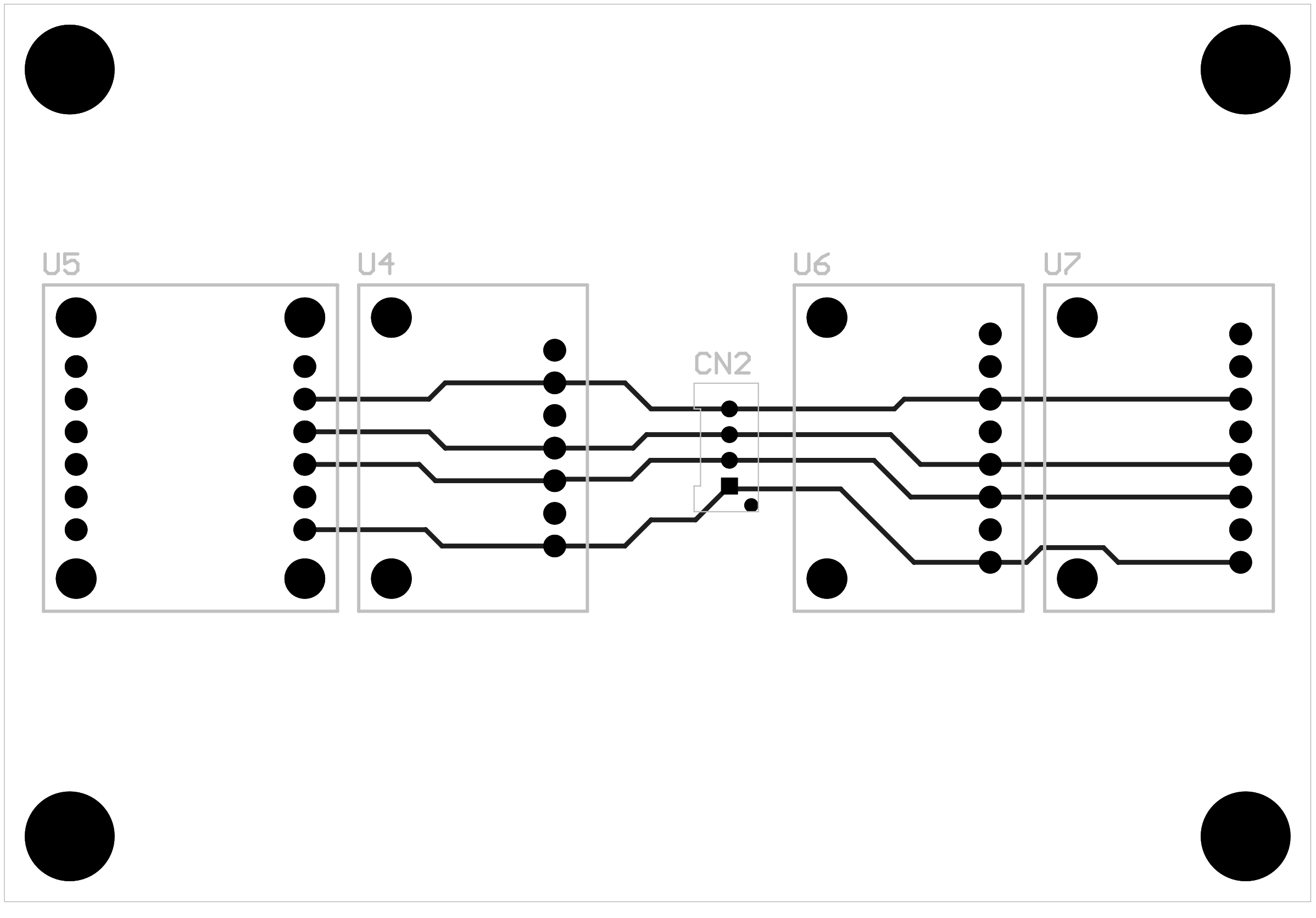
FRANC – External Peripheral Board
FRANC Communication Bus
Below is the JSON that was sent to the RPI at the 100 Hz rate, notice there is a CRC appended at the end (you may have to scroll). Some of these values do not change in between cycles, this is because the system is updating at the maximal rate that data is available in the registers.
{"timestamp":3642848,"bme_temperature":30.91231,"bme_pressure":310.4068,"bme_humidity":7.164301e-39,"bme_gas_resistance":-1.969491e27,"bme_altitude":2.983005,"ens_aqi":0,"ens_tvoc":0,"ens_eco2":0,"ens_hp0":0,"ens_hp1":0,"ens_hp2":0,"ens_hp3":0,"lsm_accel_x":-0.22014,"lsm_accel_y":-1.148555,"lsm_accel_z":9.982857,"lsm_gyro_x":-0.047647,"lsm_gyro_y":-0.001222,"lsm_gyro_z":0,"mpl_pressure":310.4068,"mpl_altitude":2.983005,"bno_accel_x":0.63,"bno_accel_y":0.83,"bno_accel_z":9.66,"bno_mag_x":-5.6875,"bno_mag_y":-13,"bno_mag_z":-26.6875,"bno_gyro_x":0.009817,"bno_gyro_y":0,"bno_gyro_z":0,"bno_euler_heading":159.3125,"bno_euler_roll":3.5625,"bno_euler_pitch":-4.75,"bno_linear_accel_x":0,"bno_linear_accel_y":0,"bno_linear_accel_z":-0.11,"bno_gravity_x":0.61,"bno_gravity_y":0.81,"bno_gravity_z":9.75,"bno_calibration_system":3,"bno_calibration_gyro":3,"bno_calibration_accel":3,"bno_calibration_mag":1,"crc":2323738228}
{"timestamp":3643658,"bme_temperature":30.91465,"bme_pressure":310.5687,"bme_humidity":7.164301e-39,"bme_gas_resistance":1.340211e9,"bme_altitude":2.983041,"ens_aqi":0,"ens_tvoc":0,"ens_eco2":0,"ens_hp0":0,"ens_hp1":0,"ens_hp2":0,"ens_hp3":0,"lsm_accel_x":-0.239282,"lsm_accel_y":-0.937986,"lsm_accel_z":9.724432,"lsm_gyro_x":-0.054978,"lsm_gyro_y":-0.031765,"lsm_gyro_z":0.023213,"mpl_pressure":310.5687,"mpl_altitude":2.983041,"bno_accel_x":0.57,"bno_accel_y":0.79,"bno_accel_z":9.63,"bno_mag_x":-5.0625,"bno_mag_y":-13.375,"bno_mag_z":-27.0625,"bno_gyro_x":0.004363,"bno_gyro_y":-0.002182,"bno_gyro_z":-0.001091,"bno_euler_heading":159.3125,"bno_euler_roll":3.5625,"bno_euler_pitch":-4.75,"bno_linear_accel_x":0,"bno_linear_accel_y":0,"bno_linear_accel_z":-0.17,"bno_gravity_x":0.61,"bno_gravity_y":0.81,"bno_gravity_z":9.75,"bno_calibration_system":3,"bno_calibration_gyro":3,"bno_calibration_accel":3,"bno_calibration_mag":1,"crc":3597366437}
{"timestamp":3643846,"bme_temperature":30.91465,"bme_pressure":310.2557,"bme_humidity":7.164301e-39,"bme_gas_resistance":1.340211e9,"bme_altitude":2.983041,"ens_aqi":0,"ens_tvoc":0,"ens_eco2":0,"ens_hp0":0,"ens_hp1":0,"ens_hp2":0,"ens_hp3":0,"lsm_accel_x":-0.239282,"lsm_accel_y":-1.081556,"lsm_accel_z":9.686147,"lsm_gyro_x":0.045204,"lsm_gyro_y":0.014661,"lsm_gyro_z":-0.031765,"mpl_pressure":310.2557,"mpl_altitude":2.983041,"bno_accel_x":0.61,"bno_accel_y":0.82,"bno_accel_z":9.55,"bno_mag_x":-6.5,"bno_mag_y":-14.0625,"bno_mag_z":-27.0625,"bno_gyro_x":-0.001091,"bno_gyro_y":0.001091,"bno_gyro_z":-0.001091,"bno_euler_heading":159.3125,"bno_euler_roll":3.5625,"bno_euler_pitch":-4.75,"bno_linear_accel_x":-0.01,"bno_linear_accel_y":0,"bno_linear_accel_z":-0.16,"bno_gravity_x":0.61,"bno_gravity_y":0.81,"bno_gravity_z":9.75,"bno_calibration_system":3,"bno_calibration_gyro":3,"bno_calibration_accel":3,"bno_calibration_mag":1,"crc":317513337}
High-level Flow
- Initialize logging
- Load configuration from
config.cfg - Override config with command-line arguments (if provided)
- Establish handshake with the Teensy over the interconnect bus
- Loop:
- Request JSON telemetry from Teensy
- Parse JSON into
MasterSensorData - Build APRS packet
- Modulate to AFSK waveform
- Write IQ samples to file or stdout
- Transmit IQ via HackRF
For detailed information regarding how APRS packets are demodulated, scroll to the APRS SDR section for an indepth view of the math background
Usage Function
static void usage(quill::Logger *logger)
{
    LOG_INFO(logger, "Usage: FRANC [options] <message>");
    LOG_INFO(logger, "  -c <callsign>   : Set callsign (e.g. N0CALL)");
    LOG_INFO(logger, "  -d <destination>: Set destination (default APRS)");
    LOG_INFO(logger, "  -p <path>       : Set path (default WIDE1-1,WIDE2-1)");
    LOG_INFO(logger, "  -o <file>       : Set output file (default stdout)");
    LOG_INFO(logger, "  -f <format>     : Set sample format (s8, f32, pcm)");
    LOG_INFO(logger, "  -v              : Enable debug messages");
    LOG_INFO(logger, "  <message>       : APRS information field");
}
This function prints help text when invalid arguments are provided.
Overriding Configuration from Command Line
void override_config_from_args(quill::Logger *logger, int argc, char *argv[], Config &config)
{
    optind = 1;
    int opt;
    while ((opt = ::getopt(argc, argv, "c:d:p:o:f:v")) != -1)
    {
        switch (opt)
        {
        case 'c': config.callsign = optarg; break;
        case 'd': config.dest = optarg; break;
        case 'p': config.path = optarg; break;
        case 'o': config.output = optarg; break;
        case 'f':
            if      (!strcmp(optarg, "s8"))  config.iq_sf = IQ_S8;
            else if (!strcmp(optarg, "f32")) config.iq_sf = IQ_F32;
            else if (!strcmp(optarg, "pcm")) config.iq_sf = PCM_F32;
            else { LOG_ERROR(logger, "Bad format: {}", optarg); exit(1); }
            break;
        case 'v': config.debug = true; break;
        default: usage(logger); exit(1);
        }
    }
    if (optind < argc) config.info = argv[optind];
}
This parses flags like callsign, destination, path, and output format. If a non-option argument remains, it’s treated as the APRS information field.
APRS Packet Build and Modulation
int run_aprs(quill::Logger *logger, const Config &config)
{
    std::string callsignUsed = config.callsign.empty() ? "KD9WPR" : config.callsign;
    std::string infoUsed     = config.info.empty()     ? "Hello from APRS" : config.info;

    auto frame     = ax25frame(callsignUsed.c_str(),
                               config.dest.c_str(),
                               (char*)config.path.c_str(),
                               infoUsed.c_str(), false);
    auto frame_nrzi = nrzi(frame);
    auto wave       = afsk(frame_nrzi);

    FILE *fout = config.output.empty() ? stdout : fopen(config.output.c_str(), "wb");
    if (!fout) { LOG_ERROR(logger, "Cannot open output file"); return 1; }

    if (config.iq_sf == PCM_F32)
        fwrite(wave.data(), sizeof(float), wave.size(), fout);
    else
        modulate(wave, fout, config.iq_sf);

    if (fout != stdout) fclose(fout);
    return 0;
}
This function:
- Builds the AX.25 UI frame
- Applies NRZI encoding
- Generates the AFSK waveform
- Writes samples to file/stdout in the requested format
Main Execution Loop
int main(int argc, char *argv[])
{
    quill::Logger *logger = initialize_logger();
    Config config = load_config("/local/franc/franc-master-control/config.cfg", logger);

    if (argc > 1) override_config_from_args(logger, argc, argv, config);

    bool handshakeSuccess = false;
    int fd = -1;

    // Handshake with Teensy
    auto startTime = std::chrono::steady_clock::now();
    while (true)
    {
        fd = interconnect_handshake(logger);
        if (fd >= 0) { handshakeSuccess = true; break; }
        if (std::chrono::duration_cast<std::chrono::seconds>(
              std::chrono::steady_clock::now() - startTime).count() > 300)
        {
            LOG_ERROR(logger, "No handshake in 5 minutes; proceeding without Teensy.");
            break;
        }
        sleep(2);
    }

    // Continuous loop
    while (true)
    {
        std::string jsonMsg = handshakeSuccess ? request_json(fd) : "";
        if (!jsonMsg.empty())
        {
            try
            {
                json j = json::parse(jsonMsg);
                if (j.contains("timestamp"))
                {
                    MasterSensorData sensorData;
                    sensorData.timestamp = j.value("timestamp", 0);
                    sensorData.bme_temperature = j.value("bme_temperature", 0.0f);
                    sensorData.ens_aqi = j.value("ens_aqi", 0);
                    config.info = "T=" + std::to_string(sensorData.bme_temperature) +
                                  " AQI=" + std::to_string(sensorData.ens_aqi);
                }
                else
                {
                    config.info = "No sensor data available";
                }
            }
            catch (std::exception &e)
            {
                config.info = "Error parsing JSON";
            }
        }

        // Generate APRS waveform and transmit
        run_aprs(logger, config);
        std::string s8File = config.output.empty() ? "pkt8.s8" : config.output;
        transmit_s8_iq_file(s8File, logger, config);

        sleep(20); // repeat every 20 seconds
    }

    if (handshakeSuccess) close(fd);
    return 0;
}
This loop:
- Reads JSON telemetry from Teensy (if available)
- Parses and maps sensor fields to a minimal APRS message
- Generates and transmits the APRS packet every 20 seconds
Key Takeaways
- AX.25 frame generation →
ax25frame() - Encoding pipeline → NRZI → AFSK
- Output formats → Signed 8-bit IQ, float32 IQ, or PCM audio
- Teensy interconnect is optional (runs without live sensor data)
- Manual mode is supported via CLI arguments
FRANC Velocity Calculation
I am including this because of how long it took me to derive the calculations for calculating max velcoity, most of this was taken from various textbooks online, AMEs should be familar with most of the concepts (I am not going to say I am understand it 100%, but I know how to integrate it into the system):
Frames and Quaternions:Let the body-frame specific force be \(\mathbf{a}_b(t)\in\mathbb{R}^3\) (accelerometer), and let \(q=[w,\ x,\ y,\ z]\) be the unit quaternion rotating body \(\to\) navigation (NED/ENU) frame. The direction cosine matrix (DCM) \(R(q)\) is: \[ R(q)=\begin{bmatrix} 1-2(y^2+z^2) & 2(xy-wz) & 2(xz+wy)\\ 2(xy+wz) & 1-2(x^2+z^2) & 2(yz-wx)\\ 2(xz-wy) & 2(yz+wx) & 1-2(x^2+y^2) \end{bmatrix}. \] Gravity compensation and navigation-frame acceleration:
Let \(\mathbf{g}_n=[0,0,g]^T\) (choose \(+z\) down if NED, or invert sign for ENU). Then: \[ \mathbf{a}_n(t)=R(q)\,\mathbf{a}_b(t)-\mathbf{g}_n. \] Velocity integration (continuous and discrete):
\[ \dot{\mathbf{v}}_n(t)=\mathbf{a}_n(t),\qquad \mathbf{v}_n(k)=\mathbf{v}_n(k-1)+\mathbf{a}_n(k)\,\Delta t. \] Vertical-rate fusion with barometry (complementary):
Let \(h(t)\) be altitude and \(v_b\) its finite-difference rate. Fuse vertical component to limit drift: \[ v_{n,z}^{\text{fused}}(k)=\alpha\bigl(v_{n,z}(k-1)+a_{n,z}(k)\Delta t\bigr)+(1-\alpha)\,v_b(k),\ \ \alpha\in(0,1). \] Baro rate (robust finite difference):
\[ v_b(k)=\frac{h(k)-h(k-1)}{\Delta t}. \] Maximum speed tracking:
\[ v_{\max}(k)=\max\bigl(v_{\max}(k-1),\ \|\mathbf{v}_n^{\text{fused}}(k)\|\bigr). \] Energy-based sanity bound (drag neglected):
Given altitude drop \(\Delta h=h_0-h(t)\) and initial speed \(v_0\), \[ v(t)\le \sqrt{v_0^2+2g\,\Delta h}\quad\text{(upper bound, no drag)}. \]
// velocity_estimator.c

#include <stdio.h>
#include <math.h>
#include <string.h>
#include <stdbool.h>

#ifndef M_PI
#define M_PI 3.14159265358979323846
#endif

typedef struct {
    // Navigation-frame velocity estimate [m/s]
    double v_n[3];
    // Last altitude for baro rate
    double h_last;
    // Max speed magnitude observed [m/s]
    double v_max;
    // Complementary gain (0..1), closer to 1 trusts IMU more
    double alpha;
    // Gravity magnitude [m/s^2] (can be set to 9.80665 or local model)
    double g;
    // Whether h_last is valid
    bool   have_h_last;
} VelEstState;

// Normalize quaternion in-place (w,x,y,z)
static void quat_normalize(double q[4]) {
    double n = sqrt(q[0]*q[0]+q[1]*q[1]+q[2]*q[2]+q[3]*q[3]);
    if (n > 0.0) {
        q[0] /= n; q[1] /= n; q[2] /= n; q[3] /= n;
    }
}

// R(q): body->nav DCM
static void quat_to_dcm(const double q[4], double R[3][3]) {
    const double w=q[0], x=q[1], y=q[2], z=q[3];
    const double xx=x*x, yy=y*y, zz=z*z;
    const double wx=w*x, wy=w*y, wz=w*z;
    const double xy=x*y, xz=x*z, yz=y*z;

    R[0][0] = 1.0 - 2.0*(yy + zz);
    R[0][1] = 2.0*(xy - wz);
    R[0][2] = 2.0*(xz + wy);

    R[1][0] = 2.0*(xy + wz);
    R[1][1] = 1.0 - 2.0*(xx + zz);
    R[1][2] = 2.0*(yz - wx);

    R[2][0] = 2.0*(xz - wy);
    R[2][1] = 2.0*(yz + wx);
    R[2][2] = 1.0 - 2.0*(xx + yy);
}

// y = R * x
static void mat3_mul_vec3(const double R[3][3], const double x[3], double y[3]) {
    y[0] = R[0][0]*x[0] + R[0][1]*x[1] + R[0][2]*x[2];
    y[1] = R[1][0]*x[0] + R[1][1]*x[1] + R[1][2]*x[2];
    y[2] = R[2][0]*x[0] + R[2][1]*x[1] + R[2][2]*x[2];
}

// Euclidean norm
static double norm3(const double v[3]) {
    return sqrt(v[0]*v[0]+v[1]*v[1]+v[2]*v[2]);
}

// Initialize state
void vel_est_init(VelEstState *st, double alpha, double g) {
    memset(st, 0, sizeof(*st));
    st->alpha = (alpha < 0.0) ? 0.0 : (alpha > 1.0 ? 1.0 : alpha);
    st->g = (g > 0.0) ? g : 9.80665;
    st->have_h_last = false;
}

// Update estimator
// Inputs:
//   q_bn: unit quaternion body->nav [w,x,y,z]
//   a_b:  body specific force [ax, ay, az] in m/s^2 (accelerometer outputs)
//   h:    altitude [m] (ENU up-positive), or NED down-negative — choose consistently
//   dt:   timestep [s]
//   use_ENU: if true, nav z+ is up (ENU). If false, z+ is down (NED). This selects gravity sign.
// Output state is updated (st->v_n[], st->v_max)
void vel_est_update(VelEstState *st, double q_bn[4], const double a_b[3],
                    double h, double dt, bool use_ENU)
{
    if (dt <= 0.0) return;

    // 1) Ensure quaternion normalized
    quat_normalize(q_bn);

    // 2) Rotate body accel to nav frame
    double R[3][3], a_n[3];
    quat_to_dcm(q_bn, R);
    mat3_mul_vec3(R, a_b, a_n);

    // 3) Subtract gravity in nav frame (z-axis only, ENU: g negative, NED: g positive)
    //    ENU: z up, gravity vector is [0,0,-g]
    //    NED: z down, gravity vector is [0,0, +g]
    a_n[2] -= (use_ENU ? -st->g : st->g);

    // 4) Integrate IMU acceleration for velocity prediction
    double v_pred[3] = {
        st->v_n[0] + a_n[0]*dt,
        st->v_n[1] + a_n[1]*dt,
        st->v_n[2] + a_n[2]*dt
    };

    // 5) Baro vertical rate (if previous altitude available)
    double v_baro = 0.0;
    if (st->have_h_last) {
        v_baro = (h - st->h_last) / dt;  // ENU: up-positive; if NED, pass a consistent h
    } else {
        st->have_h_last = true;
    }
    st->h_last = h;

    // 6) Complementary fusion for vertical component only
    //    Horizontal components remain from IMU integration.
    const double alpha = st->alpha;
    v_pred[2] = alpha * v_pred[2] + (1.0 - alpha) * v_baro;

    // 7) Commit and track max speed
    st->v_n[0] = v_pred[0];
    st->v_n[1] = v_pred[1];
    st->v_n[2] = v_pred[2];

    double speed = norm3(st->v_n);
    if (speed > st->v_max) st->v_max = speed;
}

// Example usage / simple test harness
#ifdef VELEST_MAIN
int main(void) {
    VelEstState st;
    vel_est_init(&st, 0.95, 9.80665); // trust IMU 95%, fuse 5% baro in vertical

    // If accelerometer reports +g on Z at rest in body frame, feed that and the gravity subtraction
    // will zero it out in nav frame.
    double q_bn[4] = {1,0,0,0}; // w,x,y,z
    double dt = 0.01; // 100 Hz
    bool use_ENU = true;

    // Simulated: small upward baro climb while IMU sees near-zero accel (hover-ish)
    for (int k=0; k<500; ++k) {
        double t = k*dt;
        double a_b[3] = {0.0, 0.0, 0.0};      // specific force in body (m/s^2)
        double h = 10.0 + 0.5 * t;            // altitude increasing 0.5 m/s
        vel_est_update(&st, q_bn, a_b, h, dt, use_ENU);
        if ((k % 50) == 0) {
            printf("t=%.2f v_n=[%.3f %.3f %.3f] |v|=%.3f v_max=%.3f\n",
                   t, st.v_n[0], st.v_n[1], st.v_n[2], norm3(st.v_n), st.v_max);
        }
    }
    return 0;
}
#endif
FRANC APRS SDR Logic
I understand this may be a bit much for everyone, but this was the logic behind the engineering of the APRS design, and why the code is what it is. I did not do a good job communicating exactly what was going on with the HackRF, so not much of this SDR breakdown was made available to people who would be interested in it.
APRS on VHF: How the AX.25 “Header” is Formed and Sent Over AFSK-1200
Physical layer (Bell 202 AFSK @ 1200 baud): Nominal bit rate: \[ R_b = 1200\ \mathrm{bit/s}, \quad f_\mathrm{mark} = 1200\ \mathrm{Hz}, \quad f_\mathrm{space} = 2200\ \mathrm{Hz}. \] Bit period: \[ T_b = \frac{1}{R_b} = \frac{1}{1200}\ \mathrm{s}. \] A discrete-time phase accumulator (sampling at \( f_s \)) implements: \[ \Delta\phi = \frac{2\pi f}{f_s}, \quad f \in \{f_\mathrm{mark}, f_\mathrm{space}\}, \] \[ \phi[n] = \bigl( \phi[n-1] + \tfrac{2\pi f}{f_s} \bigr) \bmod 2\pi, \quad x[n] = A\cos\phi[n]. \] With APRS/AX.25 NRZI: - A data bit 0 → tone transition - A data bit 1 → keep current tone \[ f_k = \begin{cases} f_{k-1}, & b_k = 1, \\[4pt] \text{toggle}(f_{k-1}), & b_k = 0, \end{cases} \] \[ \text{toggle}(1200) = 2200, \quad \text{toggle}(2200) = 1200. \] Occupied audio bandwidth (Carson’s rule for BFSK): \[ \Delta f = \frac{1}{2} \lvert f_\mathrm{space} - f_\mathrm{mark} \rvert = 500\ \mathrm{Hz}, \] \[ B \approx 2\bigl( \Delta f + R_b \bigr) = 2(500 + 1200) = 3400\ \mathrm{Hz}. \]Framing (HDLC over AX.25): APRS frames are AX.25 *UI* frames: \[ \underbrace{\texttt{0x7E}}_{\text{Flag}}\ \underbrace{\text{ADDR}_\mathrm{dest}\ \text{ADDR}_\mathrm{src}\ \text{ADDR}_\mathrm{digi}}_{\text{AX.25 address fields}}\ \underbrace{\texttt{0x03}}_{\text{Control = UI}}\ \underbrace{\texttt{0xF0}}_{\text{PID = No L3}}\ \underbrace{\text{APRS payload}}_{\text{Information}}\ \underbrace{\text{FCS}}_{\text{CRC-16/CCITT}}\ \underbrace{\texttt{0x7E}}_{\text{Flag}}. \] Each address subfield is 7 octets: \[ \text{ADDR} = (C_1, \dots, C_6, S), \] where \( C_i \) are the six callsign characters and \( S \) is the SSID/flags octet. Each address octet is transmitted LSB-first and left-shifted by one bit before transmission: \[ C_i' = (\mathrm{ASCII}(C_i) \ll 1), \] \[ S' = \bigl( \text{SSID/flags as specified} \ll 1 \bigr) \oplus E, \] where \( E \in \{0, 1\} \) (extension bit) is placed in the LSB, with \( E = 1 \) marking the last address in the chain.
Bit ordering, bit-stuffing, and NRZI: All bytes: LSB-first (HDLC). To avoid the flag pattern \(\texttt{0x7E}\) = \(01111110\), HDLC inserts a 0 after any run of five 1’s: \[ 11111 \ \Rightarrow\ \text{insert } 0. \] Expected stuffing overhead for random data: \[ \approx \frac{1}{32} \ (\text{about }3.125\%). \] NRZI mapping: \[ \text{NRZI}(d_k) = \begin{cases} \text{no transition}, & d_k = 1, \\[4pt] \text{transition}, & d_k = 0, \end{cases} \] which matches the tone-toggle AFSK modulation above.
From bits to samples: Let \(\mathbf{u}\) = APRS header (addresses + control + PID), \(\mathbf{p}\) = payload. Transmitted samples: \[ \mathbf{x} = \mathcal{M} \bigl( \mathcal{N}( \mathcal{C}( \mathcal{S}([\mathbf{u} \ \| \ \mathbf{p}]) ) ) \bigr), \] optionally shaped/upsampled by \(\mathcal{F}\) before D/A conversion.
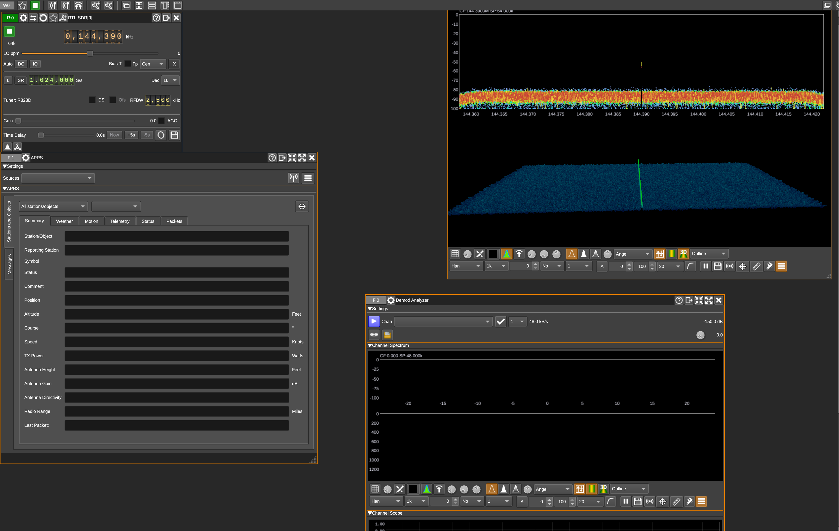
SDR Angel APRS Packet Reporting
FRANC Dipole Logic
This will describe some of the reasoning behind the antenna dynamics, a senior EE created an Ansys simulation you can page through here, and I will summarize at a high level the anntena dynamics that were considered.
Antenna Principles and System Overview:
An antenna is an electromagnetic transducer — it converts time-varying currents in its conductors into electromagnetic (EM) waves in space, and vice versa. The efficiency of this process depends strongly on the antenna's geometry, electrical length, and surrounding materials.
Dipole Length Choices:
We tested and modeled half-wave \(\frac{\lambda}{2}\) and quarter-wave \(\frac{\lambda}{4}\) dipole configurations.
Half-wave dipole:
A balanced antenna whose length is approximately: \[ L_{\frac{\lambda}{2}} \approx \frac{\lambda}{2} = \frac{c}{2 f} \] where \(c\) is the speed of light and \(f\) is the operating frequency. A half-wave dipole is self-resonant and does not require a ground plane. It has an impedance near \(73\ \Omega\) in free space, making it easy to match to \(50\ \Omega\) feedlines.
Quarter-wave monopole:
A single element of length \(\frac{\lambda}{4}\), using a ground plane (real or virtual) to act as the missing half of the dipole. Without a ground plane, the antenna is electrically incomplete and efficiency drops. The ground plane reflects the currents to form the “mirror image” half of the antenna.
Amplifier Stage:
We employed an RF power amplifier to raise the transmitter output to approximately \(5\ \mathrm{W}\). An RF amplifier boosts the voltage and current of the modulated RF carrier while preserving its waveform. Its gain \(G\) is: \[ G_{\mathrm{dB}} = 10 \log_{10} \left( \frac{P_{\mathrm{out}}}{P_{\mathrm{in}}} \right) \] High-gain amplifiers require impedance matching at both input and output to prevent reflections and loss.
Antenna System Signal Chain:
In our case, baseband telemetry from the digital subsystem is modulated into an RF waveform, amplified, and fed to the antenna. This can be expressed as: \[ \mathbf{s}_{\mathrm{BB}}(t) \xrightarrow{\ \mathcal{M}\ } s_{\mathrm{RF}}(t) = A \cos\!\big(2\pi f_c t + \phi(t)\big) \xrightarrow{\ \mathrm{PA}\ } A'(t) \xrightarrow{\ \mathrm{Antenna}\ } \mathbf{E}(r,t),\ \mathbf{H}(r,t) \] Where: \[ \begin{aligned} \mathbf{s}_{\mathrm{BB}}(t) & = \text{baseband signal (AFSK in our case)}\\ f_c & = \text{carrier frequency in the VHF band}\\ \phi(t) & = \text{phase modulation from the baseband}\\ \mathrm{PA} & = \text{power amplifier}\\ \mathbf{E},\ \mathbf{H} & = \text{far-field EM wave components} \end{aligned} \]
Carbon Fiber Effects:
Carbon fiber composites are electrically conductive and can act as unintended RF shields, especially at VHF. The fibers form a lossy conductive mesh that: \[ \begin{aligned} &\bullet\ \text{Reflects part of the wave}\\ &\bullet\ \text{Absorbs energy and converts it to heat}\\ &\bullet\ \text{Detunes nearby antennas by altering the effective dielectric environment} \end{aligned} \] A hole in the carbon fiber breaks this continuous conductive path, reducing shielding effectiveness locally. This opening provides an RF “window” through which the antenna can radiate, restoring much of the intended radiation pattern and efficiency.
Operating Band:
We are transmitting in the VHF band. For a given frequency \(f\), the free-space wavelength is: \[ \lambda = \frac{c}{f} \] For example, at \(f = 144\ \mathrm{MHz}\): \[ \lambda \approx 2.083\ \mathrm{m} \] Thus: \[ L_{\frac{\lambda}{2}} \approx 1.041\ \mathrm{m}, \quad L_{\frac{\lambda}{4}} \approx 0.520\ \mathrm{m} \] These lengths are starting points — real-world designs adjust them for velocity factor, material loading, and mounting conditions.
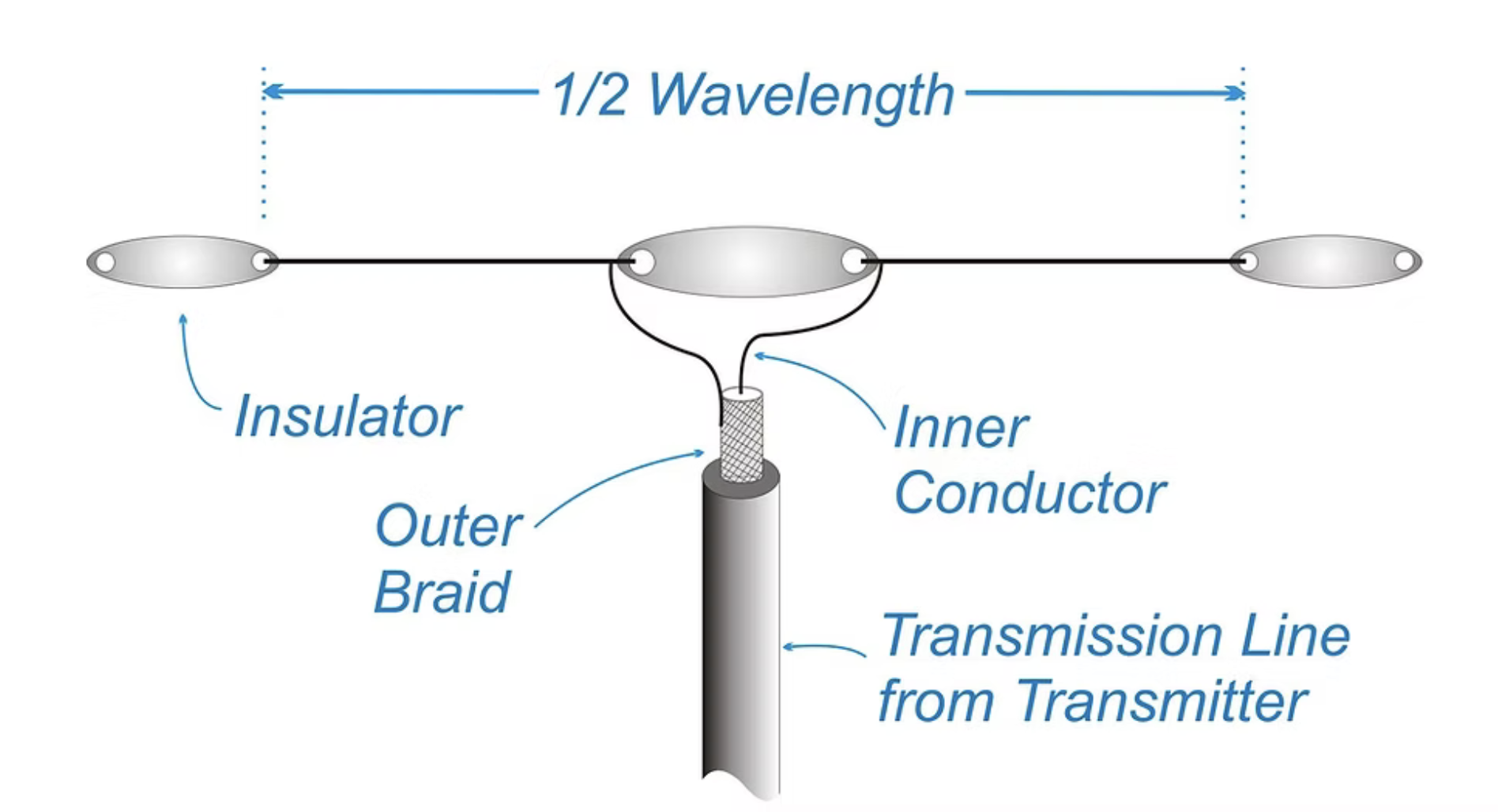
Dipole Antenna System Components
Dipole Physics
