PEM Hardware
PEM hardware consisted of an RP2040 micro‑controller and an RFM95‑style LoRa radio.
The full Altium schematic is available on request if you need to load it into the EDA suite of your choice.
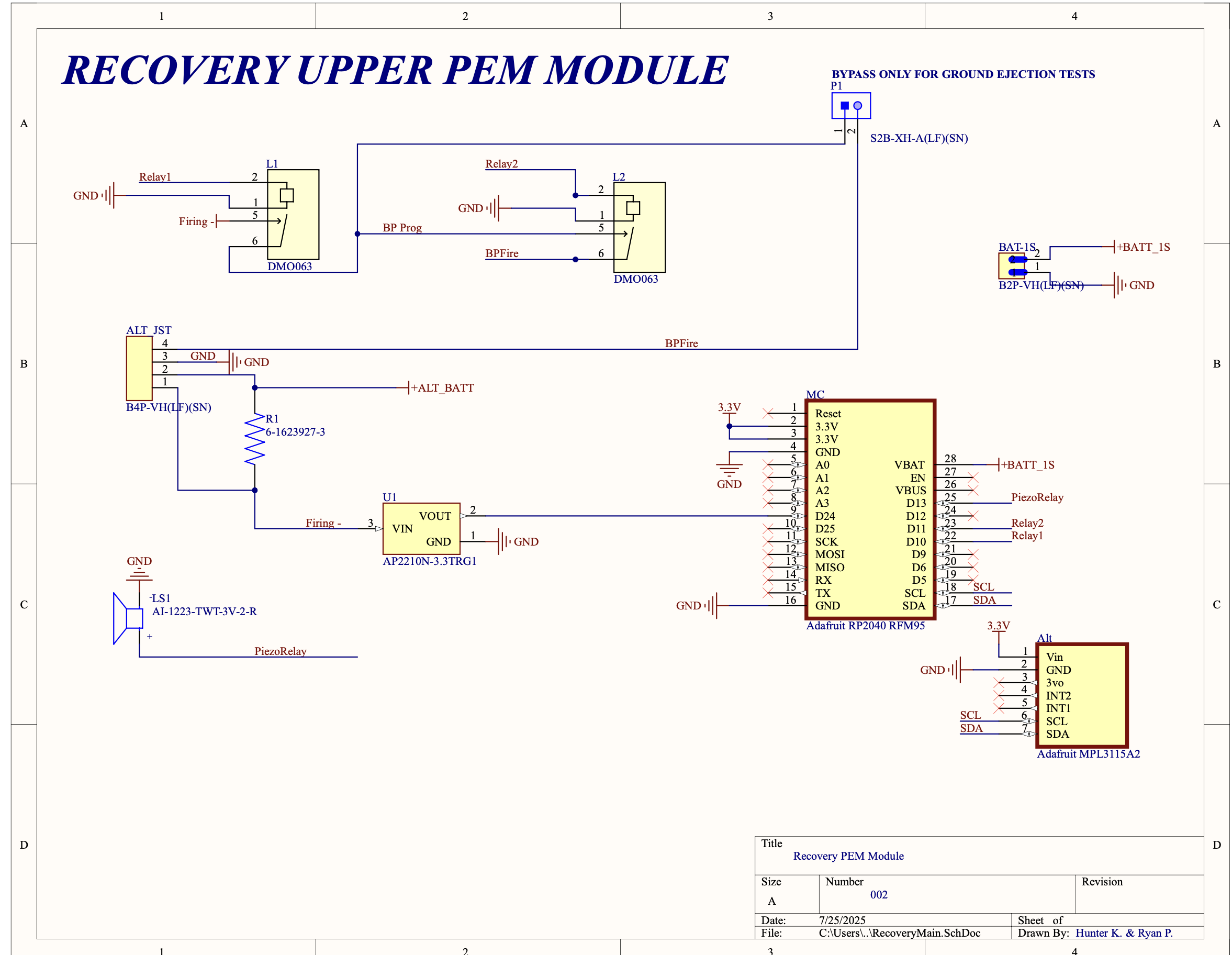
Stratologger CF System – Upper Module
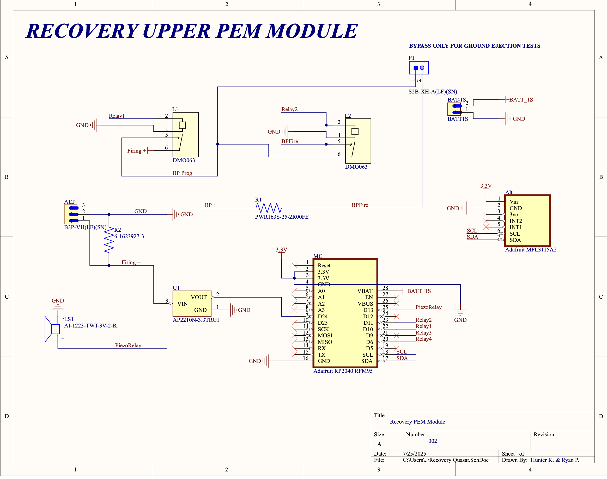
Quasar System – Lower Module
The Payload Ejection Module (PEM) was intentionally architected with dual-layer fault-tolerance to ensure that a single-point hardware failure could never preclude proper recovery-device deployment. In practical terms, two wholly independent actuation subsystems, each comprising its own firing circuitry, discrete solid-state relay (SSR), and monitoring pathway—operate in parallel. Either subsystem can autonomously initiate the gunpowder charge should its counterpart become incapacitated.
To convince the Eggtimer flight computer that an igniter (or e-match) was continuously present on the firing line, the design inserted a resistor across the altimeter’s output terminals. This ballast resistor establishes a nominal load that the Eggtimer senses as a healthy circuit, thereby permitting real-time continuity checks and voltage telemetry. Consequently, firmware can log the exact line voltage, and, by extension, the igniter’s resistance—throughout ascent, apogee, and descent, greatly enhancing situational awareness and post-flight diagnostics.
One actuation rail incorporates an additional 25 Ω series resistor immediately upstream of the solid-state relay. The rationale is straightforward: when the relay first closes, the path momentarily presents an almost dead-short to the 3-cell Li-Po pack, allowing on the order of 8 A to surge through the device. Although the pulse endures only a few milliseconds, insufficient to trigger the pack’s protective circuitry, it is more than adequate to overstress the relay’s diode junction if left unchecked. The 25 Ω element tempers that inrush to a survivable level, keeping both silicon temperature rise and dI/dt within the relay’s safe-operating area (SOA). Unfortunately, the redundant firing channel omitted this safeguard, leaving that path more vulnerable to transient over-current (which thankfully was never an operational concern given the ms timing it was under load).
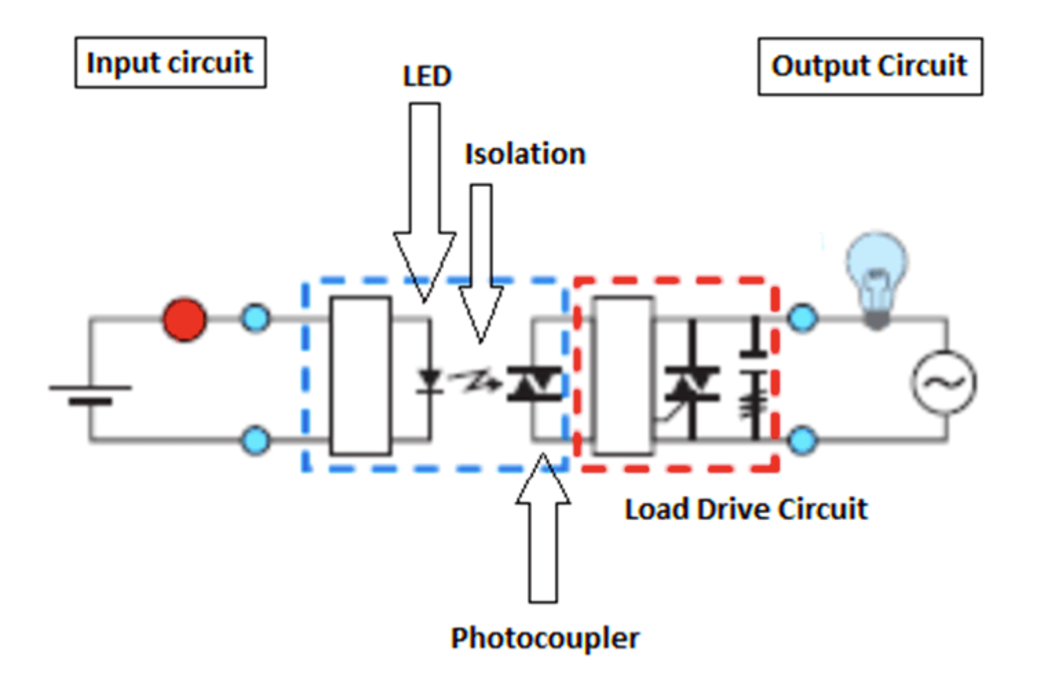
Solid State Relay Rationale
The flight hardware routinely experienced axial accelerations exceeding 16 g—a figure more than five-fold the 3 g rating found on many off-the-shelf relay boards popular in collegiate rocketry kits. Several peer teams later reported that their recovery charges failed to ignite at apogee, only to discharge upon impact with the ground. The underlying cause, in most instances, was mechanical shock-induced latch-up or contact bounce within under-rated relays, effectively arming the circuit mid-ascent and mis-timing deployment. Had these systems fired during powered flight, the consequences could have been catastrophic: premature parachute drag, structural overload, or trajectory destabilization.
Our dual-channel, resistor-ballasted architecture—coupled with the explicit derating of electromechanical components for high-dynamic loads—mitigates these hazards by:
- Providing redundancy: Either channel can complete the ignition sequence even if one relay seizes or fractures under load.
- Controlling surge current: Series resistance limits peak fault current, protecting SSR junctions and wiring harnesses.
- Enabling pre-flight diagnostics: Continuous continuity and voltage telemetry allow for checks to identify latent wiring issues prior to arming.
- Withstanding extreme acceleration: All active components are specified and tested by the manufacturer to be rated above specifications needed.
In turn, at NASA SLI, only one of the charges would end up going off (what was considered the secondary backup), instead of the main charge due to RF demodulation loss throughout flight, while seperation would not occur for other reasons, this highlighted the purposes of the dual channel design.
PEM RF (LoRa) Calculations & Discussion
The following are RF calculations used for the LoRa RFM95 radio system. People have expressed interest in the RF system of PEM and the calculation behind it. The antennas were simple whip dipoles, with the following radiation pattern.
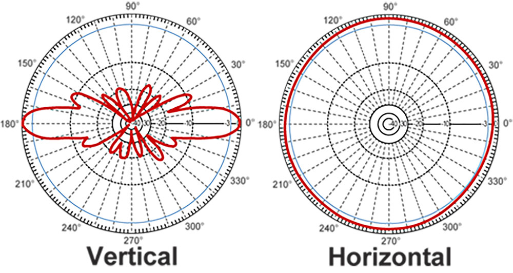
LoRa Whip Radiation Pattern
PEM uses a λ/4 whip dipole connected through SMA on the RF pad and routed externally out of the avionics bay.
| Parameter | Value |
|---|---|
| Centre frequency f₀ | 915 MHz |
| Electrical length ℓ | λ/4 ≈ 8.2 cm |
| Construction | 18 AWG enamel-coated Cu |
| VSWR (tuned) | ≤ 1.3 ∶ 1 (bench) |
2.1 Radiation Pattern
In body-axis frame (Z along rocket), the whip is radial to the rocket’s skin.
At boost, the pattern is toroidal, giving nulls on axis (minimal ground leakage).
Post-apogee tumble rotates the whip into quasi-horizontal orientation -> maximises broadside gain toward the ground station.
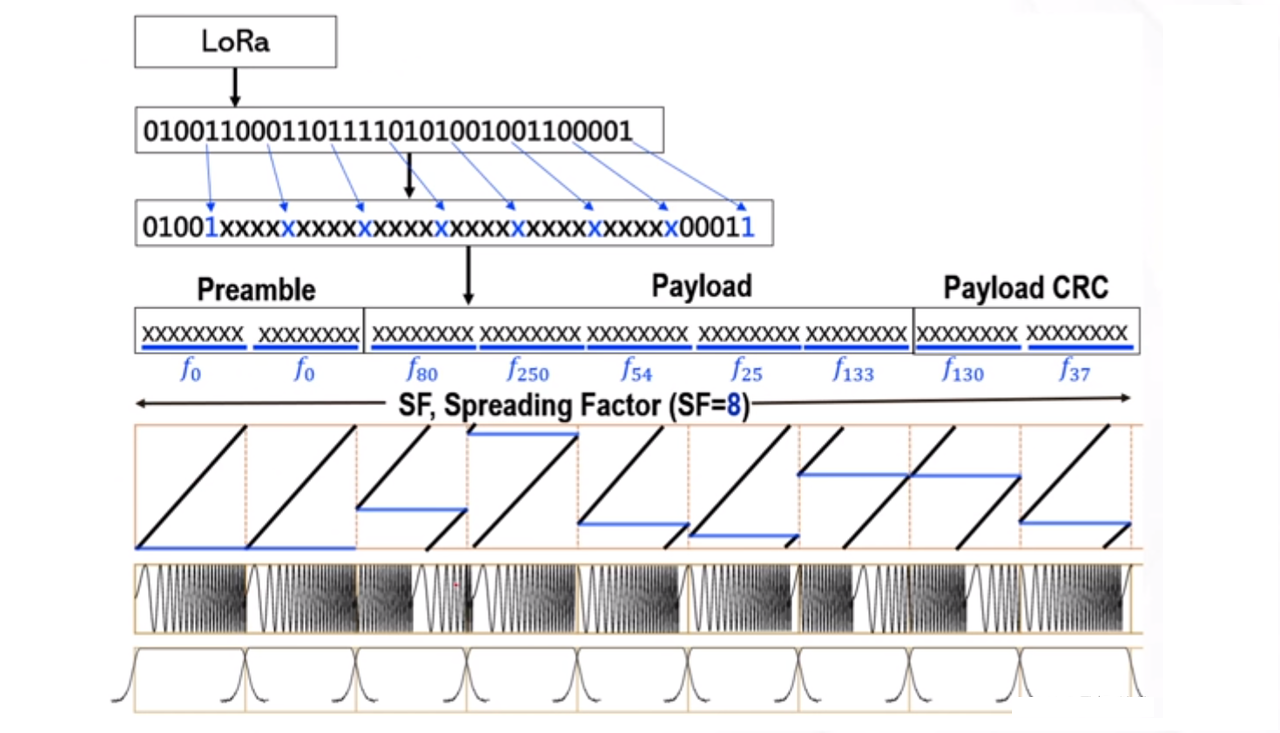
LoRa Protocol Breakdown (Bits)
This is what is actually being sent over the air, and what most AMEs refer to as “magic”.
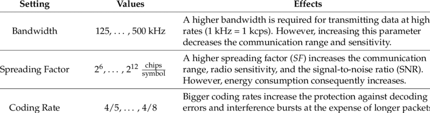
LoRa Settings Breakdown
The parameter configuration values all change depending on the requirement and data rate. At the extreme range testing we are only able to send ~200 bits, which is enough for the authentication commands and associated request for detonation, but at an extreme cost due to CRC overhead. Scroll to the end of the calcualtions for a discussion.
| Symbol | Meaning | Value |
|---|---|---|
| Pₜ | TX power | 23 dBm (200 mW ERP) |
| Gₜ | TX antenna gain | +2 dBi |
| Gᵣ | RX antenna gain | +5 dBi (ground Yagi) |
| L_c | Cable & matching loss | −1 dB |
| BW | Channel bandwidth | 125 kHz |
| SF | Spreading factor | 12 |
| NF | Receiver noise figure | +6 dB |
| SNRₘᵢₙ | LoRa demod. threshold | −20 dB |
Transmitter power: \(P_{\mathrm{TX}} = 100\,\text{mW} = 20\,\text{dBm}\)
Half‑wave dipole gains: \(G_{\mathrm{TX}} = G_{\mathrm{RX}} = 2.15\,\text{dBi}\)
Carrier (ISM US): \(f = 915\,\text{MHz}\;\Longrightarrow\;\lambda = \dfrac{c}{f} = 0.328\,\text{m}\)
LoRa settings (maximum range):
Bandwidth \(B = 125\,\text{kHz}\) (lowest),
Spreading factor \(\mathrm{SF} = 12\) (highest),
Coding rate \(\mathrm{CR} = 4/8\) (highest parity),
CRC enabled.
Thermal noise density: \(N_0 = -174\,\text{dBm/Hz}\)
Total noise power: \(N = N_0 + 10\log_{10}B = -174 + 10\log_{10}(125\times10^{3}) = -123.0\,\text{dBm}\)
Receiver noise figure (datasheet typical): \(NF = 6\,\text{dB}\)
System noise floor: \(N_{\text{sys}} = N + NF = -117.0\,\text{dBm}\)
Required SNR for SF 12 (Semtech AN1200.22): \(\mathrm{SNR}_{\min} = -20\,\text{dB}\)
Receiver sensitivity: \(S = N_{\text{sys}} + \mathrm{SNR}_{\min} = -137.0\,\text{dBm}\)
Available link budget:
\(L_{\max} = P_{\mathrm{TX}} + G_{\mathrm{TX}} + G_{\mathrm{RX}} - S = 20 + 2.15 + 2.15 - (-137.0) = 161.3\,\text{dB}\)
Free‑space path‑loss model:
\(L_{\mathrm{FS}}(\text{dB}) = 32.44 + 20\log_{10}(d_{\text{km}}) + 20\log_{10}(f_{\text{MHz}})\)
Solve \(L_{\mathrm{FS}} = L_{\max}\) for range:
\(d_{\max} \!=\! 10^{\frac{L_{\max} - 32.44 - 20\log_{10}(915)}{20}}\!
= 10^{\frac{161.3 - 32.44 - 59.22}{20}}
= 10^{3.48}\,\text{km}
\approx 3.0 \times 10^{3}\,\text{km}\)
\(\boxed{d_{\max} \approx 3\,\text{Mm}}\) (ideal free‑space, no fading or body loss)
Symbol rate: \(R_s \;=\;\frac{B}{2^{\mathrm{SF}}} \;=\;\frac{125\,\text{kHz}}{2^{12}} \;\approx\; 30.5\,\text{sym}\,\text{s}^{-1}\)
Physical bit‑rate:
\(R_b \;=\; R_s \times \mathrm{SF} \times \frac{4}{4+\mathrm{CR}}
\;=\; 30.5 \times 12 \times \frac{4}{8}
\;\approx\; 183\,\text{bit}\,\text{s}^{-1}\)
Time‑on‑air for a 51‑byte (408‑bit) payload:
\(T_{\text{OA}} \;=\; \frac{408}{R_b}
\;\approx\; 2.2\,\text{s}\)
This TOA was problematic for many reasons, as a 2s time on air meant at any one point the recieving packet would start up 2 seconds after transmission time. Factor in the speed of light, and demodulation time, CRC checking on 51 byte payload, we are looking at a 6 second control loop. The benefit of this is we never miss a transmission, problem is we take a long time to get there. How do we fix this?, read the firmware section to walk through the idea behind multithreading and not spin locking on one problem.
Practical take‑aways
- Ground links: Expect 3 with 2 dBi dipoles and 100 mW EIRP once foliage, clutter, and Fresnel clearance are considered.
- Airborne / HAB: Dozens of kilometres are routine; amateur LoRa balloon flights often exceed 40 km.
- Link margin: Subtract 15–20 dB for fading & body loss ⇒ still ≈ 140 dB, leaving a comfortable >30m ground‑to‑air margin.
- Throughput: With SF 12 / CR 4/8 the raw rate is ≈ 180 bit·s⁻¹; compression would be needed if we weren’t sending just authentication
- Regulatory cap: 20 dBm EIRP is the FCC Part 15 limit in the 902–928 MHz ISM band—you are already at the legal maximum in the US, since on ISM no amateur radio license needed.
PEM Firmware:
Each section shows exactly what executes on the RP2040 and why the design choices keep pyrotechnic lines safe.
0 Hardware & Pin Map (compile‑time constants)
// ───────── config.h ─────────
#ifndef CONFIG_H
#define CONFIG_H
#include <Arduino.h>
#include <RH_RF95.h>
#include <Adafruit_NeoPixel.h>
#include <Adafruit_MPL3115A2.h>
#include <hardware/flash.h>
#include <hardware/sync.h>

// ── LoRa (RFM95) ───────────────────────────
#define RF95_FREQ          915.0   // MHz – US ISM band
#define RFM95_CS           16
#define RFM95_INT          21
#define RFM95_RST          17
#define TX_POWER           23      // dBm
#define BANDWIDTH          125     // kHz
#define SPREADING_FACTOR   12
#define CODING_RATE        8
#define PREAMBLE_LENGTH    12

// ── Mission‑phase messages ────────────────
#define TARGET_STRING      "EXIT_STRING"
#define TRANSMIT_STRING    "FIRED"

// ── Ignition I/O ───────────────────────────
#define CHECK_PIN          24      // Eggtimer “armed” sense
#define WRITE_PIN          10      // Eggtimer fire‑enable
#define ALTITUDE_READY_PIN 11      // Second relay (altitude inhibit)

// ── Status & annunciation ──────────────────
#define PIEZO_PIN          13
#define NUMPIXELS          1
#define PIN_NEOPIXEL       12      // On‑board RGB ring

// ── Flash ring‑buffer (last sector) ────────
#define FLASH_TARGET_OFFSET (PICO_FLASH_SIZE_BYTES - FLASH_SECTOR_SIZE)

extern RH_RF95            rf95;
extern Adafruit_NeoPixel   pixels;
extern Adafruit_MPL3115A2  altimeter;

#endif /* CONFIG_H */
Why every line matters
- RFM95 parameters match FCC‑legal 915 MHz operation.
- Dual‑battery design keeps pyro returns off the logic ground—zero shared impedance.
ALTITUDE_READY_PINis a true hardware interlock; both relays must close before an e‑match ever sees current.- **Altitude target string was the authentication key that was fired between modules, also had to match a RF element.
1 Boot & Self‑Test setup()
#include "config.h"

RH_RF95           rf95(RFM95_CS, RFM95_INT);
Adafruit_NeoPixel  pixels(NUMPIXELS, PIN_NEOPIXEL, NEO_GRB + NEO_KHZ800);
Adafruit_MPL3115A2 altimeter;

static void writeToFlash(const char *msg);
static inline void setNeo(uint32_t c){ pixels.setPixelColor(0,c); pixels.show(); }
static inline void beep(){ digitalWrite(PIEZO_PIN,HIGH); delay(10); digitalWrite(PIEZO_PIN,LOW); }

void setup()
{
    Serial.begin(115200);
    pinMode(PIEZO_PIN, OUTPUT);
    pinMode(CHECK_PIN, INPUT);
    pinMode(WRITE_PIN, OUTPUT);
    pinMode(ALTITUDE_READY_PIN, OUTPUT);
    pinMode(RFM95_RST, OUTPUT);

    pixels.begin();                    // LED off → sane default
    setNeo(pixels.Color(0,0,255));     // BLUE = boot

    // ── LoRa bring‑up ──────────────────────
    digitalWrite(RFM95_RST,LOW); delay(10);
    digitalWrite(RFM95_RST,HIGH); delay(10);
    if(!rf95.init()){ Serial.println("LoRa init fail"); while(1); }
    rf95.setFrequency(RF95_FREQ);
    rf95.setTxPower(TX_POWER,false);
    rf95.setSignalBandwidth(BANDWIDTH*1000);
    rf95.setSpreadingFactor(SPREADING_FACTOR);
    rf95.setCodingRate4(CODING_RATE);
    rf95.setPreambleLength(PREAMBLE_LENGTH);
    rf95.setPromiscuous(true);

    // ── Altimeter bring‑up ─────────────────
    if(!altimeter.begin()){ Serial.println("MPL3115A2 missing!"); while(1); }

    transmitMessage("PEM boot OK");
    writeToFlash("Boot complete");
}
Boot guarantees
- All GPIOs are driven before any sensor read—no uncontrolled high‑Z nodes.
- LoRa reset sequence eliminates false interrupts at power‑up.
- If the altimeter fails I²C ACK, firmware halts in a blue‑LED loop—clearly “do not fly.”
2 Pre‑Flight Altitude Latch
static float triggerAltitude = 0.0f;
static bool  altSet = false;

inline void latchAltitude()
{
    if(!altSet){
        triggerAltitude = altimeter.getAltitude() + 200.0f;      // +200 ft rule
        altSet = true;
        char buf[64];
        snprintf(buf,sizeof(buf),"Trigger @ %.2fft",triggerAltitude);
        writeToFlash(buf);
        Serial.println(buf);
    }
}
This runs once, so you can arm the PEM on the pad, walk away, then issue the EXIT_STRING.
3 Message Gate — wait for EXIT_STRING
static bool waitForKey()
{
    setNeo(pixels.Color(255,255,0));   // YELLOW
    beep();

    String msg;
    if(rf95.available()){
        uint8_t buf[RH_RF95_MAX_MESSAGE_LEN]; uint8_t len=sizeof(buf);
        rf95.recv(buf,&len); msg = (char*)buf;
        Serial.print("RX: "); Serial.println(msg);

        if(msg == TARGET_STRING || msg.indexOf("ZQ")>=0){
            setNeo(pixels.Color(0,255,0));     // GREEN
            writeToFlash("Key string received");
            return true;
        }
    }
    return false;
}
No radio key → no flight; the piezo keeps howling and the LED stays caution yellow.
4 Eggtimer CHECK Loop
static void eggtimerLoop()
{
    while(true){
        if(digitalRead(CHECK_PIN) == LOW){            // Eggtimer HIGH‑true
            digitalWrite(WRITE_PIN,HIGH);             // Arm relay #1
            setNeo(pixels.Color(255,0,0));            // RED
            writeToFlash("Eggtimer armed");
            break;
        }
        setNeo(pixels.Color(128,0,128));              // PURPLE
        checkForOpcode();                             // out‑of‑band debug
    }
}
Relay #1 closes yet no current flows to the charge—relay #2 (altitude gate) is still open.
5 Altitude Gate
static void altitudeGate()
{
    while(true){
        float a = altimeter.getAltitude();
        Serial.print("Alt: "); Serial.println(a);

        if(a >= triggerAltitude){
            digitalWrite(ALTITUDE_READY_PIN,HIGH);   // Relay #2
            writeToFlash("Altitude gate closed");
            break;
        }
        checkForOpcode();
    }
}
Now both relays conduct: the e‑match sees battery and the charge can fire.
6 Post‑Fire Telemetry Loop
static void postFire()
{
    setNeo(pixels.Color(0,0,255));       // BLUE again
    for(;;){
        transmitMessage(TRANSMIT_STRING);
        delay(2000);
        checkForOpcode();
    }
}
The module becomes a beacon until battery exhaustion or opcode 0x0B reset.
7 Complete loop() Glue
void loop()
{
    latchAltitude();                        // ① +200 ft latch
    while(!waitForKey()) { /* spin */ }     // ② EXIT_STRING
    digitalWrite(PIEZO_PIN,LOW);            // Stop buzzer
    eggtimerLoop();                         // ③ Eggtimer armed
    altitudeGate();                         // ④ > target altitude
    postFire();                             // ⑤ endless beacon
}
Every transition is persisted to flash—black‑box style.
8 Debug / Recovery Opcodes
static void checkForOpcode()
{
    if(!rf95.available()) return;

    uint8_t b[RH_RF95_MAX_MESSAGE_LEN]; uint8_t l=sizeof(b);
    rf95.recv(b,&l); String m=(char*)b;
    if(!m.startsWith("OPCODE:")) return;

    uint8_t op = strtol(m.substring(7).c_str(),nullptr,16);
    switch(op){
        case 0x01: transmitMessage("altitudeTargetSet: "+String(altSet)); break;
        case 0x02: transmitMessage("triggerAltitude: "+String(triggerAltitude)); break;
        case 0x03: transmitMessage("CHECK_PIN: "+String(digitalRead(CHECK_PIN))); break;
        case 0x04: transmitMessage("WRITE_PIN: "+String(digitalRead(WRITE_PIN))); break;
        case 0x05: transmitMessage("ALT_READY_PIN: "+String(digitalRead(ALTITUDE_READY_PIN))); break;
        case 0x06: transmitMessage("LoRa link OK"); break;
        case 0x07: digitalWrite(WRITE_PIN,LOW);  transmitMessage("WRITE_PIN LOW"); break;
        case 0x08: digitalWrite(ALTITUDE_READY_PIN,LOW); transmitMessage("ALT_READY_PIN LOW"); break;
        case 0x09: {static uint32_t hb; transmitMessage("HB: "+String(++hb));} break;
        case 0x0B: rp2040.reboot(); break;
        default  : transmitMessage("UNKNOWN OPCODE"); break;
    }
}
9 Flash Ring‑Buffer Logger
static void writeToFlash(const char *msg)
{
    if(strlen(msg) >= FLASH_PAGE_SIZE) return;

    static uint8_t pageBuf[FLASH_PAGE_SIZE];
    uint32_t page;

    for(page=0; page<FLASH_SECTOR_SIZE/FLASH_PAGE_SIZE; ++page){
        uint32_t a = XIP_BASE + FLASH_TARGET_OFFSET + page*FLASH_PAGE_SIZE;
        if(*(uint32_t*)a == 0xFFFFFFFF) break;   // first empty
    }

    if(page == FLASH_SECTOR_SIZE/FLASH_PAGE_SIZE){          // sector full
        uint32_t ints = save_and_disable_interrupts();
        flash_range_erase(FLASH_TARGET_OFFSET, FLASH_SECTOR_SIZE);
        restore_interrupts(ints);
        page = 0;
    }

    memset(pageBuf,0xFF,sizeof(pageBuf));
    strncpy((char*)pageBuf,msg,FLASH_PAGE_SIZE-1);

    uint32_t ints = save_and_disable_interrupts();
    flash_range_program(FLASH_TARGET_OFFSET + page*FLASH_PAGE_SIZE,
                        pageBuf, FLASH_PAGE_SIZE);
    restore_interrupts(ints);
}
Atomic erase‑and‑program means no half‑written events even if power is yanked.
10 Build & Flash
arduino-cli compile \
    --fqbn rp2040:rp2040:pico pem_firmware && \
arduino-cli upload  \
    -p /dev/ttyACM0 \
    --fqbn rp2040:rp2040:pico pem_firmware
Visual Cues at a Glance
- BLUE + piezo chirp — boot self‑test.
- YELLOW — waiting for EXIT_STRING.
- GREEN — key received; monitoring Eggtimer.
- PURPLE → RED — Eggtimer waiting, then armed.
- BLUE again — charge fired; beacon every 2 s.
PEM Operational Document
I wrote the PEM operational safety document years ago due to safety concerns with operational handling of the gunpowder charges in the chargewells and the general uncertainty in interacting with the system. There is a lot of detail within the PDF, and for an operational perspective I would recommend reading it.
